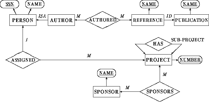
Figure 1: An Extended Entity-Relationship Diagram Example
EER schemas can be expressed in a diagrammatic form called EER Diagram. Entity-sets, relationship-sets, and attributes are represented graphically by rectangles, diamonds, and ellipses, respectively. Every vertex is labeled by the name of the object-set or attribute it represents; entity and relationship vertices must be uniquely identified by their labels globally, while attribute vertices must be uniquely identified by their labels only locally, with respect to their object-set.
Edges in an EER diagram are directed and represent the interaction of the various object-sets and attributes. Thus, there are edges:

Figure 1: An Extended Entity-Relationship Diagram Example
If entity-set E has an association-cardinality of one (respectively many) with respect to relationship-set R, then the edge connecting the vertices representing E and R is associated with label 1 (respectively M). Mandatory involvement of entity-sets in relationship-sets is represented graphically in an EER diagram by double-line edges instead of the regular edges representing the non-mandatory (optional) involvements.
Figure 1 contains an example of an EER diagram consisting of the following main elements: PERSON, AUTHOR, PROJECT, REFERENCE, PUBLICATION, and SPONSOR are entity-sets, relationship-set AUTHORED represents the association of authors with references, relationship-set ASSIGNED represents the assignment of projects to persons, HAS represents the project-sub-project relation, and SPONSORS represents the sponsoring of projects. PERSON represents a generalization of entity-set AUTHOR. The association cardinalities of relationship-set ASSIGNED represent the restriction of a project being assigned to at most one person.