Assignment 1
1.Image Alignment
1.1 Description
In this assignment we experimented with techniques for aligning separate color plates for images in order to make a color image using matlab. The goal is to align the plates so that there is no color fringing or ghosting as the boundaries of regions. We considered translations of the plates by integer numbers of pixels and performed experiments with multiple metrics for evaluating the quality of an alignment. We did experiments using images from the Prokudin-Gorskii Collection as well as some color plates we found on the web.
1.2 Algorithm and Implementation
The basic algorithm used was a simple exhaustive search over offsets for a plate in order to align it to another plate. In order to make things run faster subsampling at multiple scales was applied to the images.
Here is the algorithm:
- Chop off the 3 negatives of the same size from the input image. Note the order of the 3 negatives are B,G,R rather than R,G,B!
- Cut off the margins of each negative as output size in order to not consider the corner case pixels when moving the image. (variable 'margin' is at least variable 'range').
- Translate R,G,B matrices to be 'double' for computing.
- Move matrix G (B) by increment from '-range' to 'range' to get temp_G (temp_B)
- Use R as template, compute differences between temp_G and R (temp_B and R) to get matrix error_G (error_B).
- Find the indices of the minimum in matrix error_G (error_B).
- Move B and G by those indices of minimums, and get aligned output picture.
-
Here is parts of the code ... error_G = zeros(2*range+1,2*range+1); temp_G = zeros(height-2*margin,width-2*margin); for x=-range:range for y=-range:range temp_G(1:height-2*margin,1:width-2*margin) = G(margin+1+x:height-margin+x,margin+1+y:width-margin+y); error_G(range+1+x,range+1+y)=sum(sum((template-temp_G).^2)); end end ... [row_G,col_G] = find(error_G == min(error_G(:))); [row_B,col_B] = find(error_B == min(error_B(:))); output = zeros(height-2*margin,width-2*margin,3); output(:,:,1) = R(margin+1:height-margin,margin+1:width-margin); output(:,:,2) = G(margin+1+row_G-range-1:height-margin+row_G-range-1,margin+1+col_G-range-1:width-margin+col_G-range-1); output(:,:,3) = B(margin+1+row_B-range-1:height-margin+row_B-range-1,margin+1+col_B-range-1:width-margin+col_B-range-1); output=uint8(output); - Full version of the code of basic alignment is photog_a1.m. 'range' specifies the range of pixel shift. Please rename the input triple image as 'a1_input.jpg'.
1.3 For more complex assignment there may be additional description of the method
1.3.1 Consider small rotations
I use the function 'imrotate' to rotate the image by a given theta angle, which is in '-angle_range' to 'angle_range'. The difference is that the error matrices are now 3-D instead of 2-D, --x, y, plus theta. All the other steps are similar to the previous one.
Full version of the code that considers rotations is photog_a1_rotate.m. 'angle_range' specifies the rotation angle range. Please rename the input triple image as 'a1_input.jpg'.
1.3.2 Consider shifting a fraction of a pixel
I defined a factor to specify how fine the fraction is, and make the matrices several times larger than the original one depending on the factor, and then do the one pixel shifting version alignment. Finally, re-size the result back to the original size.
For example, the increment is half a pixel. Then, the factor is 2. We will make, for example, a 100*100 matrix to be a 200*200 one. Every 2*2 elements in the new matrix equal to the corresponding element in original matrix. After do the alignment procedure for the new matrix, I re-size the result matrix to 100*100 by making each element in the 100*100 matrix as the average of corresponding 2*2 elements in the 200*200 matrix.
Full version of the code that considers rotations and considers shifting a fraction of a pixel is photog_a1_final.m. 'fraction_factor' specifies that the pixel fraction increment is 1/fraction_factor pixel. Please rename the input triple image as 'a1_input.jpg'.
1.4 Result Images
1.4.1 Aligning images from Sergey Prokudin-Gorskii Collection<
 | 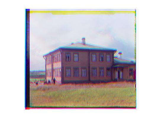 | 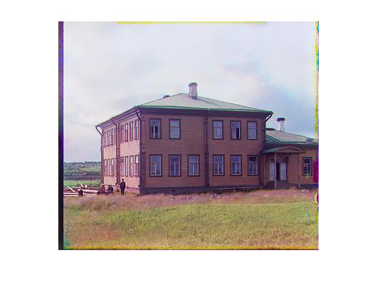 |
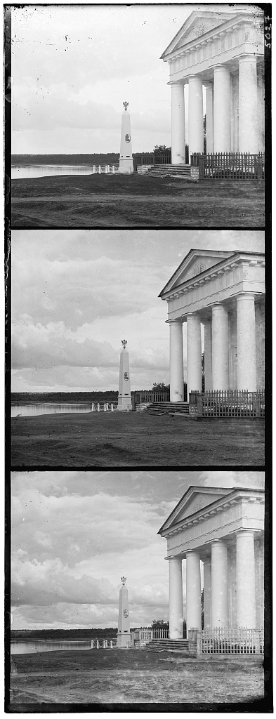 | 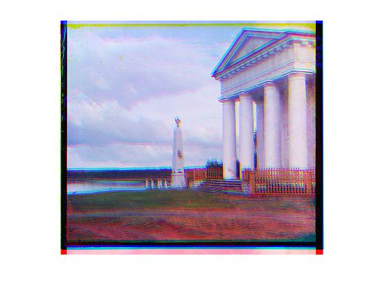 | 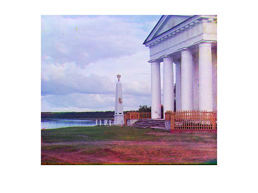 |
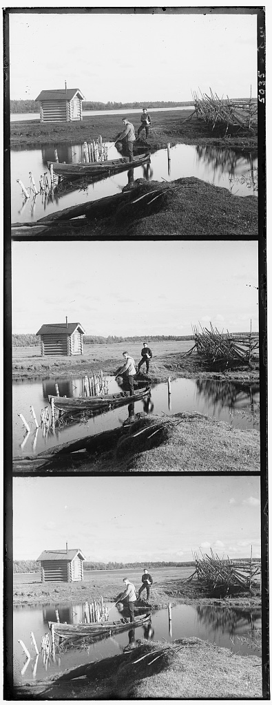 | 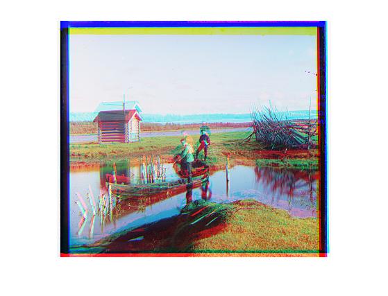 | 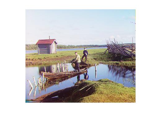 |
1.4.2 Some Discussion
There are three version of the code to align the pictures, namely photog_a1.m, photog_a1_rotate.m and photog_a1_final.m. The later, the more considerations, but the more computation time is needed. Generally, we find the first version is good enough for the pictures from the database, and it runs significantly faster.
Also, for the last version, since I double the matrix size and then cut off the margin and finally re-size it back, the output will look like cut less margin.
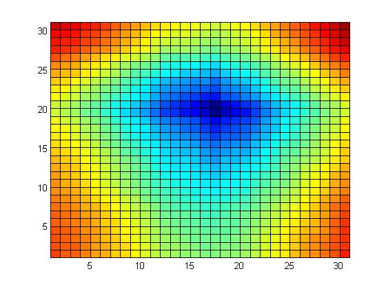
Wow, it all works! We might have added some intermediate results, like this visualization of the error as a function of offset for one of the plates. It would have been better with a "colorbar" legend to explain the meaning of the colors.
error_G for input2
 |
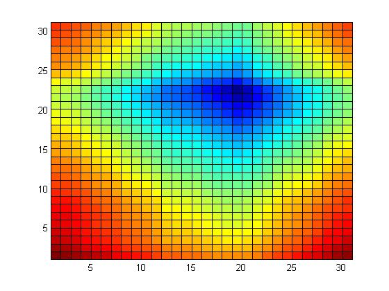
error_B for input2
 |