 |
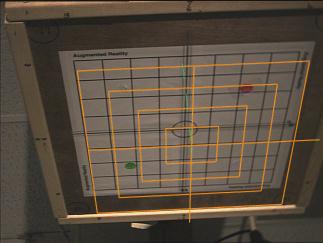
Figure 1a
AR display showing a computer-generated grid (orange) superimposed onto a
real-world grid, using uncorrected position and orientation readings from an
Ascension Flock of Birds magnetic tracker. The poor registration is due
partly to the difficulty of calibrating a camera with anything other than a
perfect tracker.
|
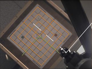 |
Figure 1b
AR display using high-precision Faro Technologies Metrecom arm for camera
tracking. The foreground elements on the right belong to the mechanical
arm. Note the correct registration of both the grid and the arm's
coordinate system at the center of the metal sphere (thick white lines).
|
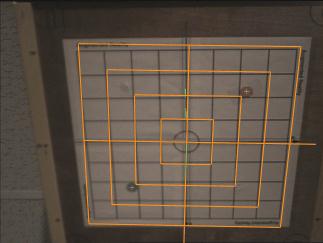 |
Figure 2a
AR display using partially corrected Ascension Technology Flock of Birds
tracking system. Two beacons (marked by small white cross hairs) are used to
correct camera orientation. The position reading from the tracker is used
for the viewpoint for the computer graphics. Note the poor registration due
almost entirely to the incorrect position reported by the magnetic tracker.
|
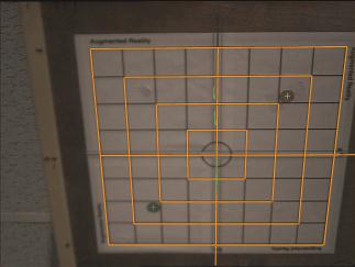 |
Figure 2b
AR display using fully corrected Ascension Technology Flock of Birds
tracking system. Two beacons (marked by small white cross hairs) are used to
correct camera orientation. The position readings from the magnetic tracker
are first corrected by the look-up table method.
|
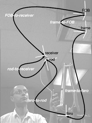 |
Figure 3
Setup for collection of samples in our lab, annotated with
transformations used. The FOB-to-receiver transformation is reported by the
FOB. The Faro-to-rod transformation is reported by the Faro arm. All other
depicted transformations are determined by calibration procedures (see
text).
|
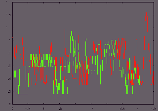 |
Figure 4a
Noise from the FOB with no motion of Faro arm (red) and motion of
Faro arm (green): relative position error (mm) versus time (sec).
Hash marks are every 0.2 mm and 0.5 sec.
|
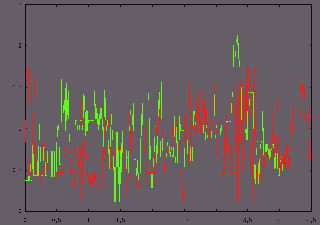 |
Figure 4b
Noise from the FOB with no motion of Faro arm (red) and motion of
Faro arm (green): relative orientation error (deg) versus time (sec).
Hash marks are every 0.5 deg and 0.5 sec.
|
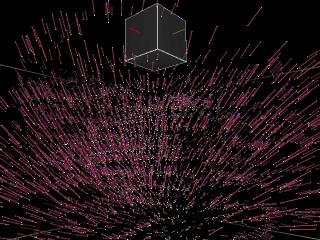 |
Figure 5a
3D view of the position error at the collected samples.
|
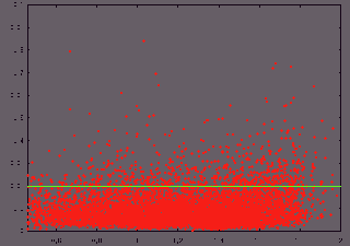 |
Figure 5b
Noise in position readings from the FOB as a function of distance from the
transmitter.
Hash marks are every 0.2 m (starting at 0.4 m) for distance and every 0.01 m
(starting at 0.0 m) for noise.
|
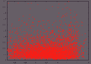 |
Figure 5c
Noise in orientation readings from the FOB as a function of distance from
the transmitter.
Hash marks are every 0.2 m (starting at 0.4 m) for distance and every 0.01 m
(starting at 0.0 m) for noise. See text for how the orientation noise is
measured.
|
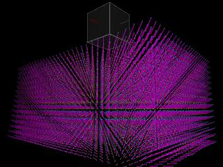 |
Figure 6a
Calibration table at half resolution, with the same viewpoint as in Figure 5a.
|
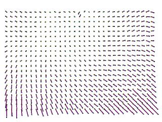 |
Figure 6b
The y=0 plane of the table.
|
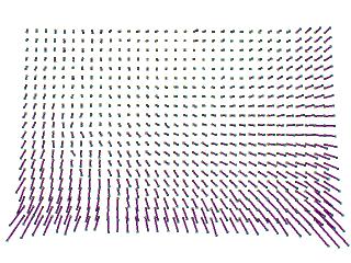 |
Figure 6c
The x=0 plane of the table.
|
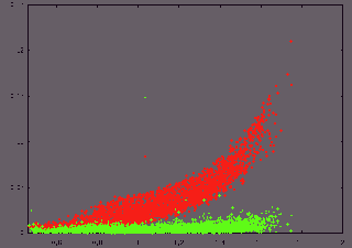 |
Figure 7a
Verifying the validity of the correction method. This graph shows
only that the table accurately reflects the raw samples. Position error
as a function of distance before and after correction. Before correction, the
average position error is 38.1 mm and the maximum position error is 238 mm.
After correction, the average is 5.0 mm and the maximum is 149 mm.
Hash marks start at 0.4 m and increment by 0.2 m for distance from
transmitter, and start at 0.0 m and increase by 0.05 m for orientation
error.
|
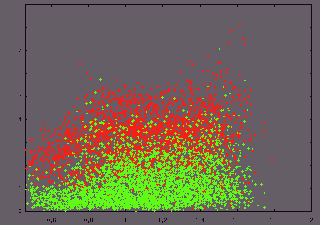 |
Figure 7b
Verifying the validity of the correction method. This graph shows only that
the table accurately reflects the raw samples. Orientation error as a
function of distance before and after correction. Before correction, the
average orientation error is 3.1 deg and the maximum orientation error is
8.1 deg. After correction, the average error is 1.3 deg and the maximum
error is 7.1 deg.
Hash marks start at 0.4 m and increment by 0.2 m for distance from
transmitter, and start at 0 deg and increase by 1 deg for orientation
error.
|
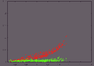 |
Figure 8a
Results from the correction method. Position error as a function of
distance before and after correction. Before correction, the average
position error is 28.7 mm and the maximum position error is 108 mm. After
correction, the average is 6.1 mm and the maximum is 23.1 mm.
Hash marks start at 0.4 m and increment by 0.2 m for distance from
transmitter, and start at 0.0 m and increase by 0.05 m for orientation
error.
|
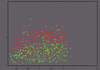 |
Figure 8b
Results from the correction method. Orientation error as a function of
distance before and after correction. Before correction, the average
orientation error is 3.5 deg and the maximum orientation error is 6.64 deg.
After correction, the average error is 2.1 deg and the maximum error is
6.55 deg.
Hash marks start at 0.4 m and increment by 0.2 m for distance from
transmitter, and start at 0 deg and increase by 1 deg for orientation
error.
|
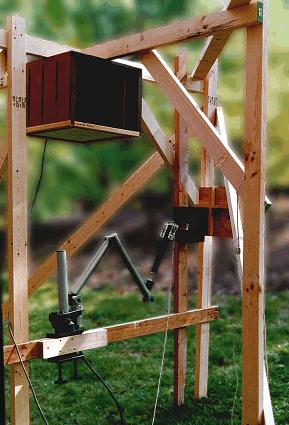 |
Figure 9
Picture of support structure used to conduct the experiment outside.
|
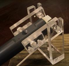 |
Figure 10
Apparatus to allow (limited) freedom in orientation while maintaining
(nearly) constant position.
|
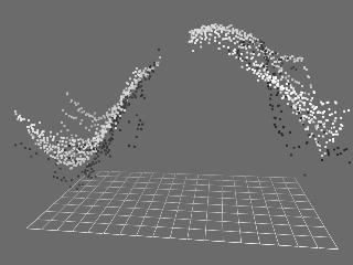 |
Figure 11
Graph of orientation error as a function of the azimuth and elevation
angles of the receiver. The longer axis of the reference grid is the azimuth
angle, ranging from -180 degrees to 180 degrees with lines every 20 degrees.
The shorter axis is elevation, ranging from -90 degrees to 90 degrees, with
lines every 20 degrees. The hole in the graph corresponds to the position of
a wooden support structure used; no significance should be attributed to it.
|