
Now that we’re familiar with the Digital software simulator and combinational logic circuit design techniques (e.g., truth tables, sum of product (SOP) expressions, and SOP simplification using Karnaugh maps), it’s time to take things to the next level! In this lab, you’re going to be wiring up a 7-segment LED Display!
The starter code for each subsequent lab will be added directly into the same course repository. To update your individual repo, navigate to your workspace on the GitHub website and you should see a “Sync Fork” button. Click this and then “Update Branch.” Now if you run ``git pull’’ in your terminal, you will have all the materials you need.
IF YOU SEE AN OPEN PULL REQUEST BUTTON when you attempt to sync your workspace, please follow the below steps. If you have any trouble, come see the TAs in office hours and we will walk you through it!
In your terminal run:
ls ~/.sshIf you see a public key file (for example id_rsa.pub
or id_ed25519.pub), you already have an SSH key. You can
print it with:
cat ~/.ssh/id_rsa.pubIf you have a key, skip to step 2 (Add the key to GitHub).
In your terminal run:
ssh-keygen -t rsa -b 4096Press Enter to accept the default file location when prompted.
Enter a passphrase you will remember.
Print the public key:
cat ~/.ssh/id_rsa.pubCopy the output to add to GitHub (see step 3 below).
cat ~/.ssh/id_rsa.pub.In your local course repo run:
git remote add starter git@github.com:comp311-fa25/comp311-fa25-comp311-fall-2025-workspace-311-fa25-starter.gitVerify remotes:
git remote -vYou should see both origin and
starter.
Pull updates from the starter remote using rebase:
git pull starter main --rebaseRepeat step 4 every time we push a new lab directory to the starter repo.
The first time you make changes and try to push to your
workspace, you may need to run
git push origin main --force.
If anything fails (SSH permission errors, etc.), see a TA in office hours for hands‑on help.
Seven-segment displays are widely used in digital clocks, electronic meters, basic calculators, and other electronic devices that display numerical information. They get their name because there are seven different lights that turn on or off depending on what number or letter is being displayed. The image below shows how a 7-segment display can be used to represent the numbers 0-9.
The display we are working with in this lab can display the digits
0-9 and the letters A-F. To control the value
being shown, the display takes as an input a 4-bit binary number. The
hexadecimal value of this 4-bit binary input is the character that will
be displayed. For example, if the input is 0b1010, the
letter A will be displayed. If the input is
0b0101, the number 5 will be displayed.
The 4 bits of the input are denoted as A, B, C, and D. For example,
if the input is 0b1010, then A = 1, B = 0, C = 1, D =
0.
The name of each segment is shown below (Fa,
Fb, Fc, Fd, Fe,
Ff, Fg). You will create separate circuits to
control each of the segments. If a segment should be on, the output of
the driving circuit should be 1. If a segment should be off, the output
of the driving circuit should be 0. For example, if the input to the
display is 0b0000, we want to display the character
0, so Fa, Fb, Fc,
Fd, Fe, and Ff would all be 1 and
Fg would be 0.

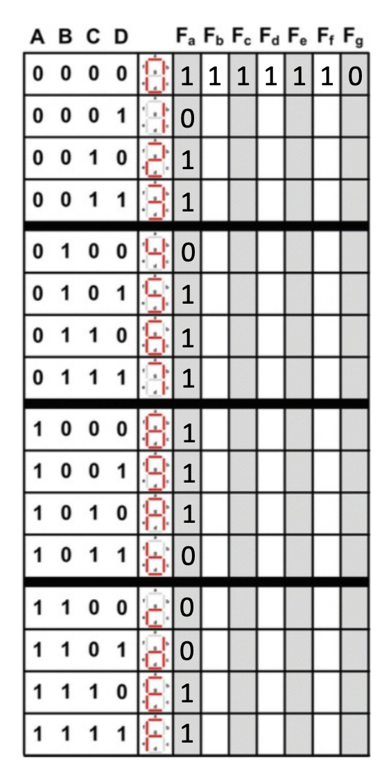
To construct the circuit that controls the 7-segment display, you will need to fill out the provided truth table. The first row and first column of the outputs in the truth table have been filled out for you.
Using the given truth-table.csv file in the repo, fill
in the rest of the truth table. Determine for each number or letter
which of the 7 LED’s will be on (1) or off (0). When you finish the
truth table, commit your changes and submit to Gradescope to see if it
is correct. If you have an incorrect truth table, your circuits in the
next part will not be correct!
Now that we’ve constructed the truth table, it’s time to get ready to build the circuit! Before we start diagramming on Digital, we need to figure out how we’re going to wire up the 7-segment display.
Using the completed truth table, create simplified Boolean expressions for each of the output segments Fa - Fg. We recommend using K-maps. When you are finished, you should have 7 Boolean equations (one for each segment in the display).
You will implement your 7 circuits in Lab02.dig. In this
file, you are provided with 4 input pins labeled A, B, C, and D. You are
also provided with 7 output pins labeled Fa, Fb,
Fc, Fd, Fe, Ff,
Fg. You may move these pins around, but DO NOT CREATE NEW
PINS.

The image below shows where to connect each of your circuits to the display. Note that the bottom right input on the display must connect to ground.

Assignments are submitted through Gradescope.
Lab02.dig).main
branch.