The starter code for each subsequent lab will be added directly into the same course repository. To update your individual repo, navigate to your workspace on the GitHub website and you should see a “Sync Fork” button. Click this and then “Update Branch.” Now if you run ``git pull’’ in your terminal, you will have all the materials you need.
OR
If you went through the additional git set-up steps for
lab 1, you should be able to run
git pull starter main --rebase
Then all the new code for lab3 should be there!
In this lab, you will be the designing the 32-bit ALU we have been studying in class up to this point! Note, we will have to make some modifications to match the 32-bit RISC-V instructions we will introduce soon, but this is a good start. :)
You will start by designing the three sub-units. Then, you will bring them all together to create a functional ALU!
We will begin by building our Boolean Unit!
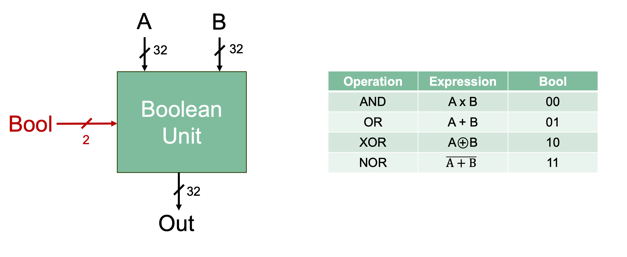
Implement your 32-bit Boolean unit based on the specification provided in the table above.
boolean-unit.dig already has the named inputs and
outputs that your circuit must use. DO NOT change the names of the
inputs and outputs.
Data Bits.Number of Selector Bits. How many inputs does the mux in
the Boolean unit need? How is the number of inputs related to the number
of selector bits?A local tester for the Boolean Unit is provided. This video explains how the tester works.
Data Bits.Time to build our Bidirectional Shifter!

Implement your 32-bit Shifter Unit based on the specification provided in the table above.
bidirectional-shifter.dig already has the named inputs
and outputs that your circuit must use.
You will be use a component called Barrel shifter which
can be found in Components → Arithmetic → Barrel
shifter.

in
in, the
following description will appear: “Input with bits to be shifted.” This
corresponds to the B input of our ALU.shift
A input of our
ALU.shift = ceil(log2(bit width of input in + 1)).
For example, if the width of in is 15, then the bit width
of shift would be ceil(log2(15 + 1)) = 4. You will need to
use a splitter to make the bit width of the input A
compatible with the shift input of the barrel shifter. The
amount we shift by will be the lower bits of A.A single barrel shifter can only perform one type of shift, so you will need three barrel shifters in your design: one will perform an arithmetic right shift, one will perform a logical right shift, and one will perform a left shift.
To choose the type of shift, right click on the barrel shifter and
alter the Direction and Mode:
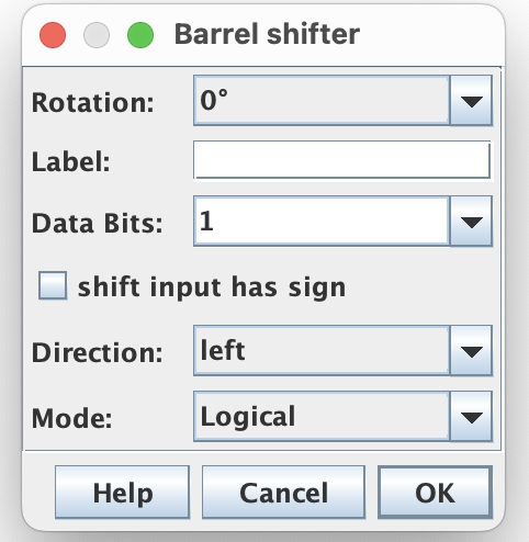
Label field.A local bidirectional shifter unit tester is provided. The tester works the same as it did for the Boolean Unit.
The tester expects that if Bool = 0b01, the output will be 0 (as
shown in the diagram at the top of this section). You can either use the
ground component or a constant to set the
output to 0. Remember to update the bit width of these components.
Onto our third sub-unit the Add/Sub unit!
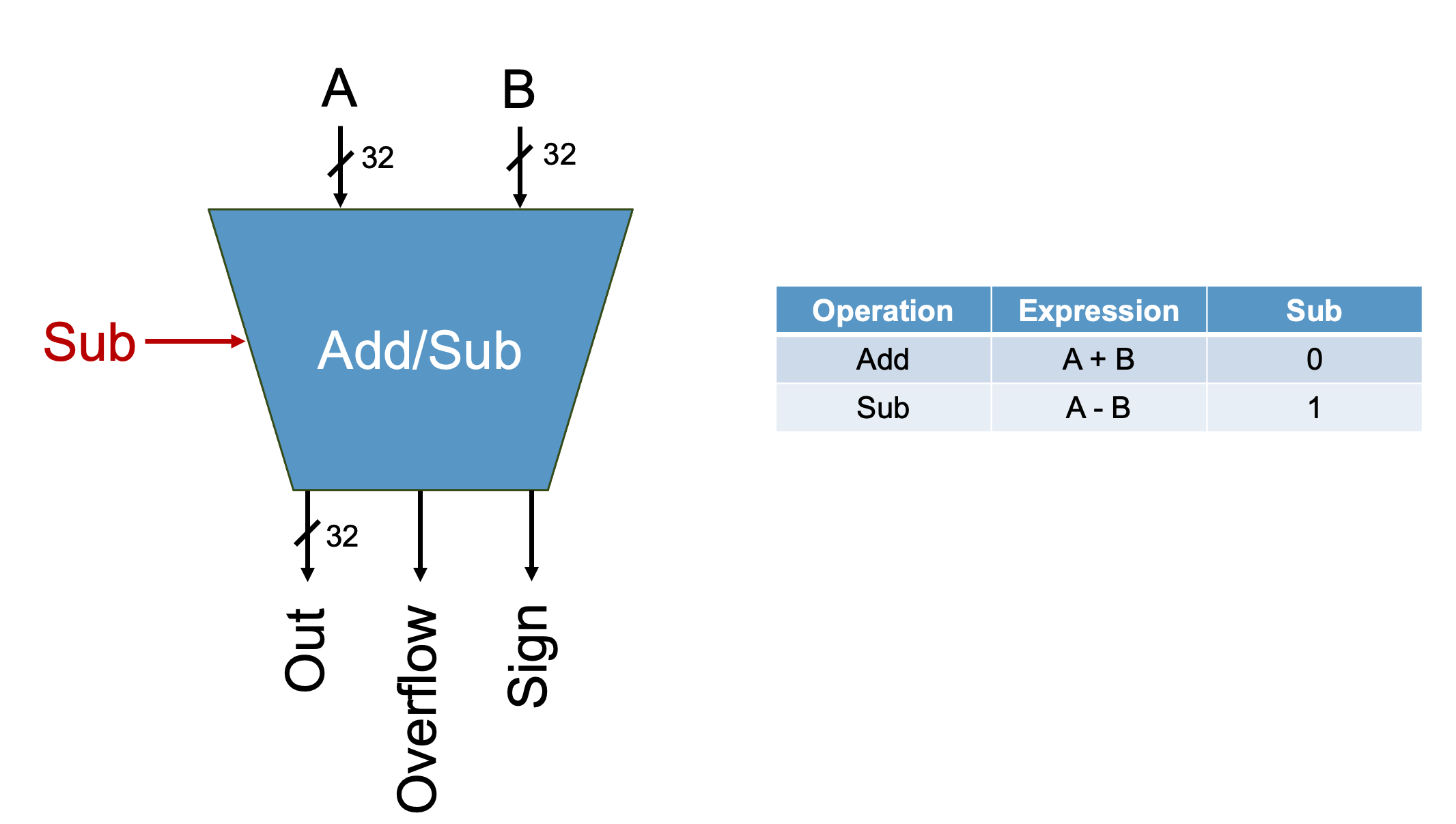
Your completed add/sub unit should output: - The result of your
arithmetic operation - The Sign of your result - Whether or
not Overflow has occurred
The new outputs Sign and Overflow are
explained below.
add-sub.dig already has the named inputs and outputs
that your circuit must use.
You will use the Adder component to implement addition.
Make sure you update the bit width of the adder.

Digital also has a component named Subtract, however you
are NOT allowed to use it. Doing so will fail the
autograder.
To implement subtraction, you will use the same method we studied in class: to perform the operation A - B, you negate B and then add it to A.
Sign is a one bit output that indicates the sign of our
result. If Sign is 1, the result is negative. If
Sign is 0, the result is positive.
Sign of Out |
Value of Sign |
|---|---|
| positive | 0 |
| negative | 1 |
Overflow is a one-bit output that will indicate if the
operation overflowed. If Overflow is 1, overflow occurred.
If Overflow is 0, overflow did not occur.
How do we know if overflow occurred? Recall the following information from COMP 211:
| Operation | Overflow occurs when |
|---|---|
| Adding two positive numbers | The result is negative |
| Adding two negative numbers | The result is positive |
| Adding two numbers of opposite signs | Overflow will never occur |
Adding two positive values should yield a positive result, so if the result is negative, this indicates that overflow has occurred. Adding two negative values should yield a negative result, so if the result is positive, this indicates that overflow has occurred. When adding numbers with opposite signs, overflow is not possible, as the sum always remains within the representable range of values for the given number of bits.
Ok, so we know how to detect overflow for additions. What about subtractions? Well, the circuit we built only performs addition (to perform subtraction, we negate B and add it to A), so we only need to know how to detect overflow when performing addition.
To implement the circuit that will detect overflow, start by filling out the table below. Then generate your equation and build your circuit!
| Sign of A | Sign of B | Sign of Result | Overflow? |
|---|---|---|---|
| 0 | 0 | 0 | |
| 0 | 0 | 1 | |
| 0 | 1 | 0 | |
| 0 | 1 | 1 | |
| 1 | 0 | 0 | |
| 1 | 0 | 1 | |
| 1 | 1 | 0 | |
| 1 | 1 | 1 |
A local add-sub unit tester is provided. It works the same as the testers for the previous components.
We recommend that you test incrementally. Implement the features in the order provided below. Test each feature before moving onto the next one. Following this process will save you a lot of headaches!
This video provides guidance on testing your add-sub unit incrementally.
Out value. Ignore Sign and
Overflow for now.Out value for both addition and subtraction. Ignore
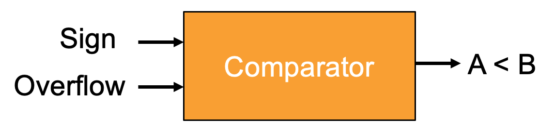
Sign and Overflow for now.Sign.Overflow.We would like our ALU to perform the operation A < B.
If the input A is less than B, the result will be 1. If A
is greater than or equal to B, the result will be 0. We
will design a new unit called Comparator to perform this
operation!
Implement the Comparator Unit as specified above.
comparator.dig already has the named inputs and outputs
that your circuit must use.
To determine if A is less than B, we subtract B from A and analyze the result. Specifically, if A−B yields a negative result, this indicates A is less than B. Conversely, a positive result implies A is greater than or equal to B.
When we want to perform A < B, we’ll set the control
signal Sub to 1 to perform A-B. The outputs
from the add/sub unit you designed earlier, Sign and
Overflow, will serve as inputs to our comparator.
Now, you might be thinking, “can’t I just look at Sign
to know if A is less than B?” That would be fine except in the case
where A - B overflows. If A-B overflows, and
Sign is 0, then A is less than B, and if Sign
is 1, then A is not less than B. This bevahior is summarized in the
table below.
| Overflow | Sign | A < B? |
|---|---|---|
| 0 | 0 | 0 |
| 0 | 1 | 1 |
| 1 | 0 | 1 |
| 1 | 1 | 0 |
Using the table, generate the Boolean equation for detecting overflow and then implement your compator circuit.
A local comparator unit tester is provided. It works the same as the testers for the previous components.
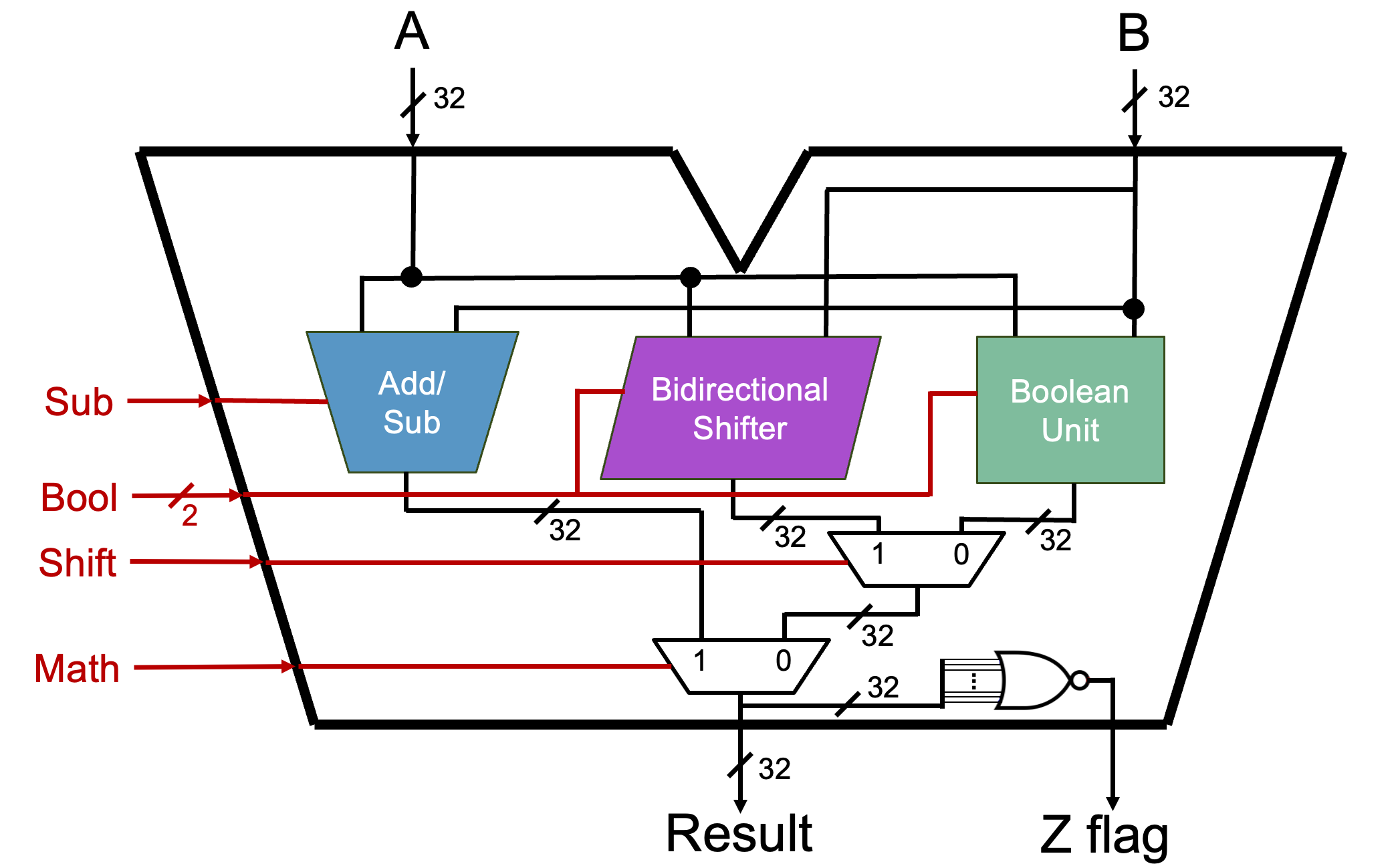
It is now time to start building our ALU! Here is the full implementation of our ALU with the comparator unit included:

The schematic provided in alu.dig already has the named
inputs and outputs that your circuit must use.
The ALU unit should be able to: - Perform the following operations -
addition - subtraction - A < B (this operation is known as set on
less than or SLT) - left shift - logical right shift - arithmetic right
shift - bitwise AND - bitwise OR - bitwise XOR - bitwise NOR - Output if
the result is zero on FlagZ.
To add a custom component, navigate to Components → Custom → “component-name”. Add your Add-Sub Unit, Bidirectional Shifter, Boolean Unit, and Comparator.
Now it’s time to wire everything up! Please save yourself a huge headache and use tunnels.
The comparator produces a 1-bit output. The result of the ALU is 32 bits. To make the bit widths compatible, you will need to zero-extend the output of the comparator to be 32-bits. You can do this with the splitter/merger component.
If the ALU is performing the operation A < B: - If A
is less than B, Result = 0x00000001 - If A is not less than B, Result =
0x00000000
FlagZ, known as the Zero Flag, checks if
the result of our ALU is 0. If the result is zero, FlagZ is
1, otherwise FlagZ is 0. You can find the comparator in
Components → Arithmetic → Comparator:
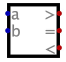
It is important to note that this component may NOT
be used when computing A < B. This will result in the
failing of the autograder.
Make sure you set the data bits of the comparator to 32!!!
A local ALU unit tester is provided. It works the same as the testers for the previous components.
Assignments are submitted through Gradescope.