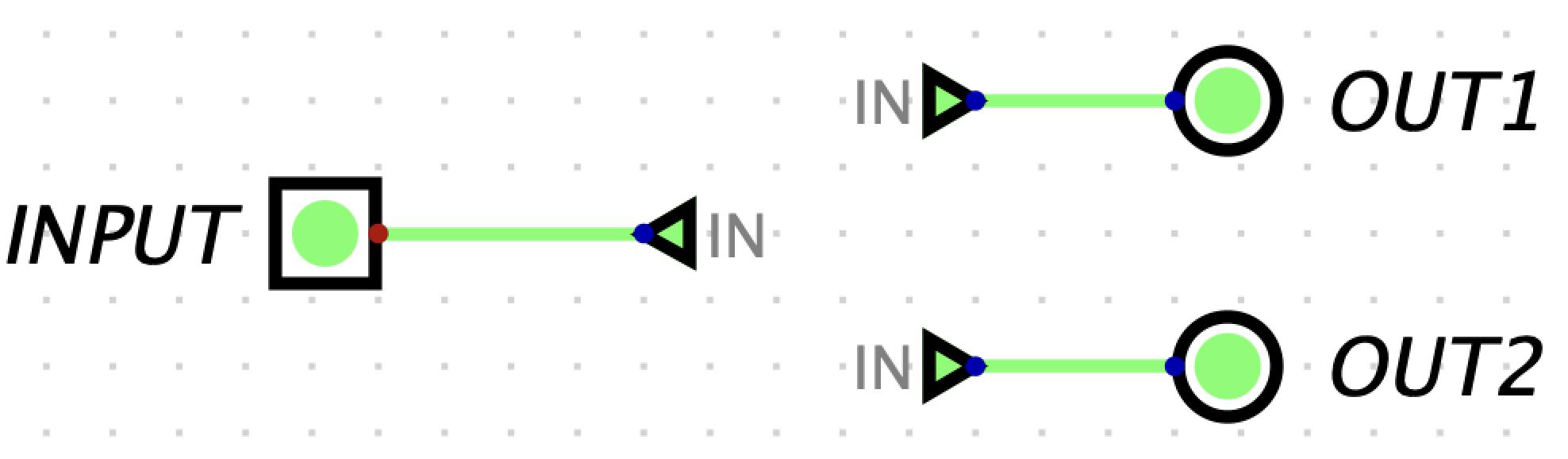
Tunnels are a feature that will both save you a lot of time debugging and make your circuits look much cleaner.
A tunnel allows you draw an “invisible wire” to bind two points together. Tunnels are grouped by case-sensitive labels. They are used to connect wires like so:
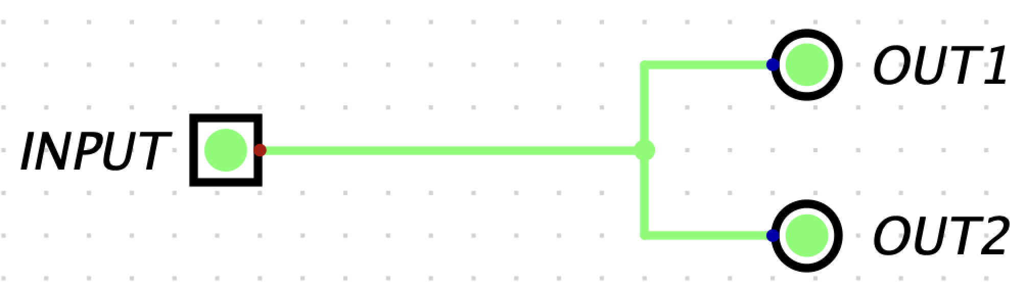
which effectively is:
If a wiring connection is invalid, the wires will turn red as seen below.
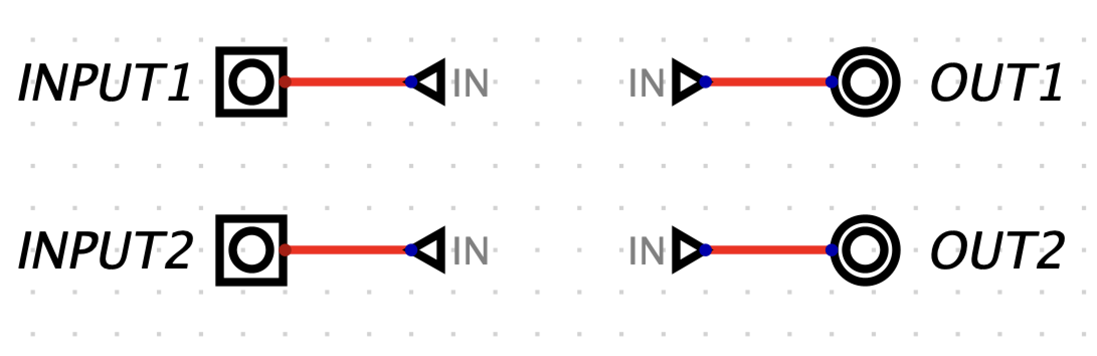
The above circuit is equivalent to the circuit below.
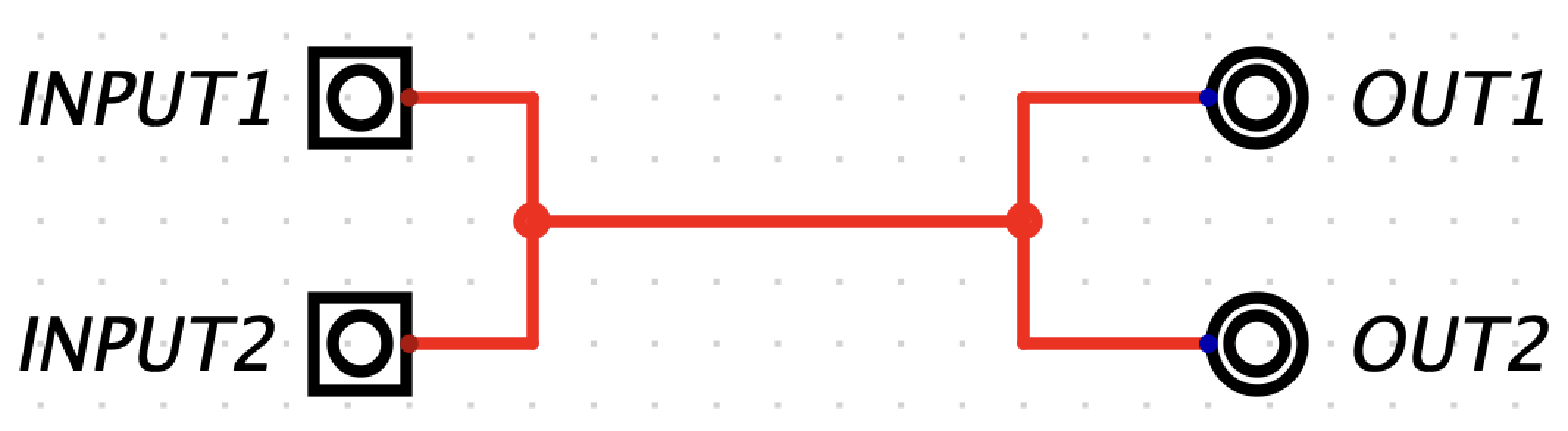
This circuit is invalid because two different inputs are trying to drive the same signal.
We strongly recommend you use tunnels when working in Digital because they make your circuits much cleaner (less wiring spaghetti), which means easier debugging.
Let’s look at an example of how helpful tunnels are in cleaning up a
circuit schematic. You can find the schematic below in
ex1-example.dig.
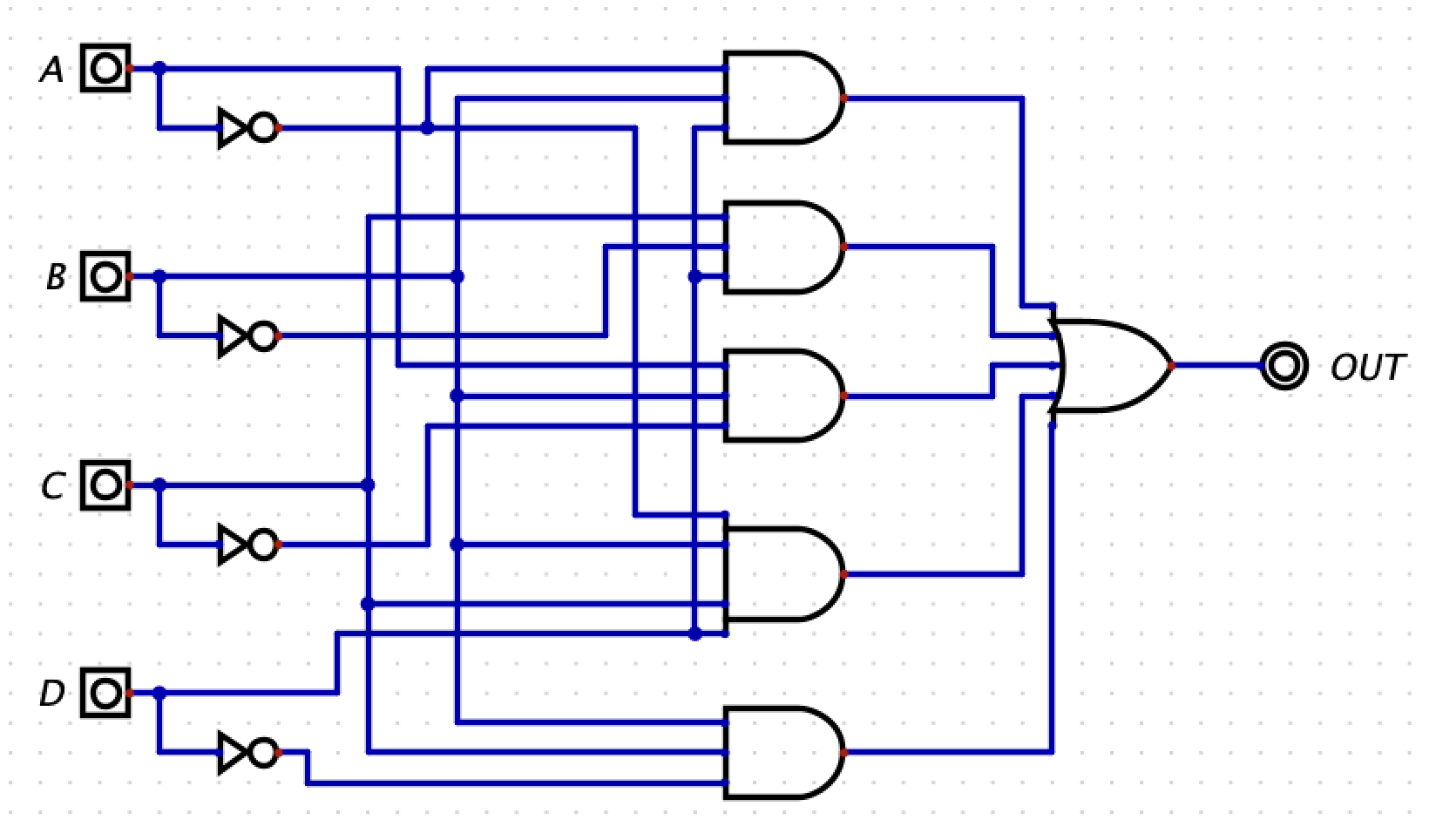
The above schematic is hard to read and would be difficult to debug
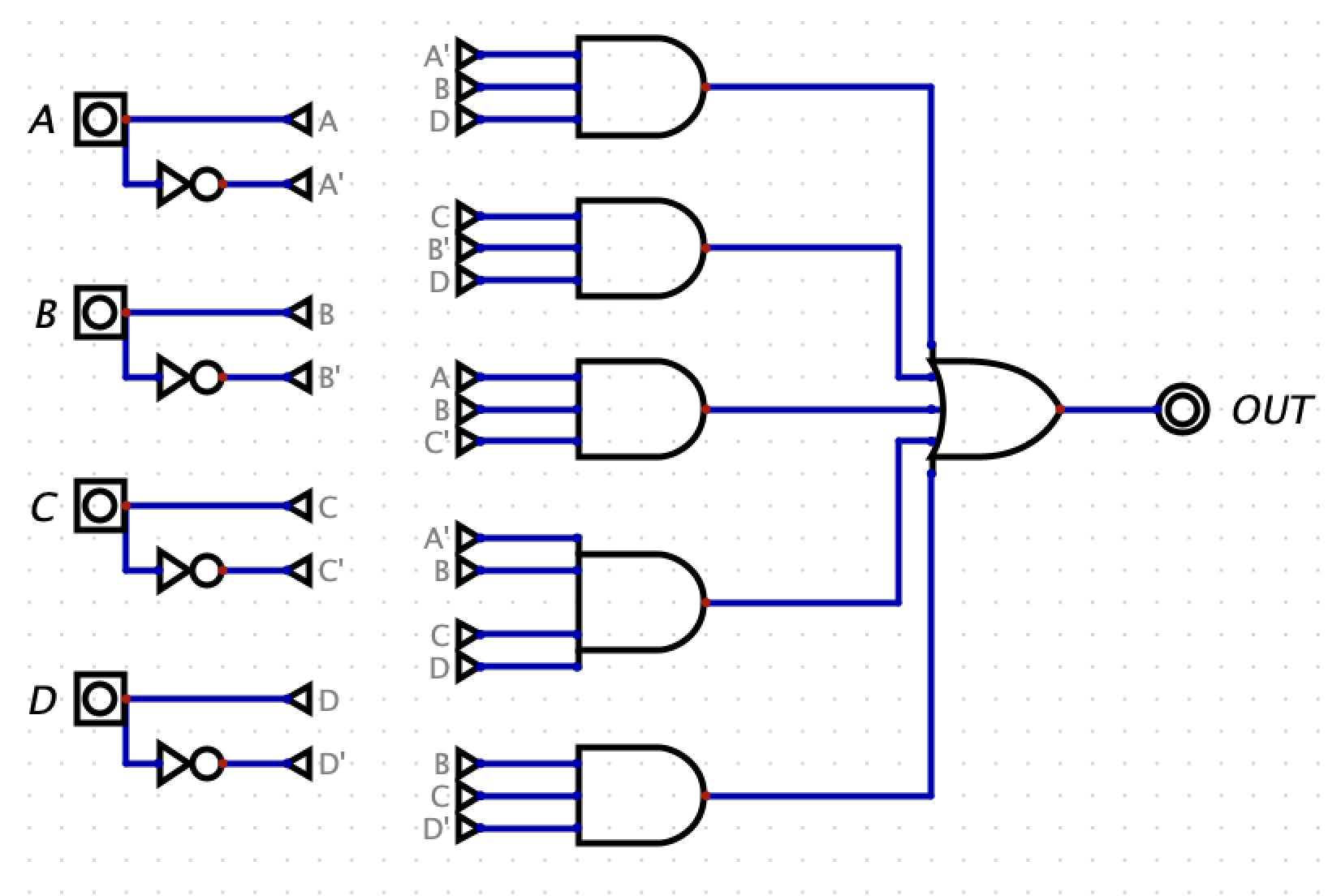
if there was an error. Below is the same circuit but making use of
tunnels. You can see that it is much easier to read this circuit
diagram. You can find the schematic below in
ex1-example-tunnels.dig.
Now it’s time for you to try! Clean up the circuit schematic below by
using tunnels. You can find this schematic in ex1.dig.
Place your solution here.
Tip: To rotate a tunnel, select the tunnel and click the
r key.
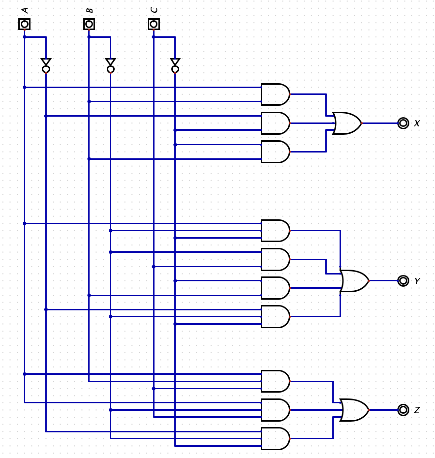
A test fixture is included for you to verify the functionality of your circuit. To run the test fixture, click Simulation -> Run Tests.
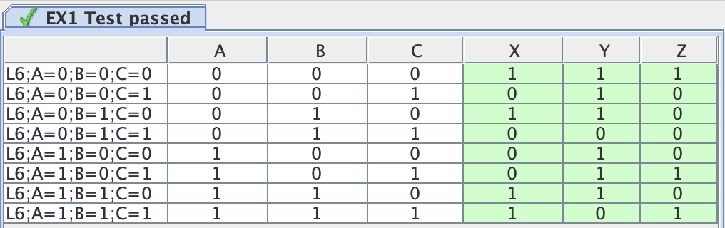
A new window should appear showing you the results. This test is verifying that X, Y, and Z are the correct values for each combination of A, B, and C. If you pass all test cases, all outputs will be highlighted in green as shown below.
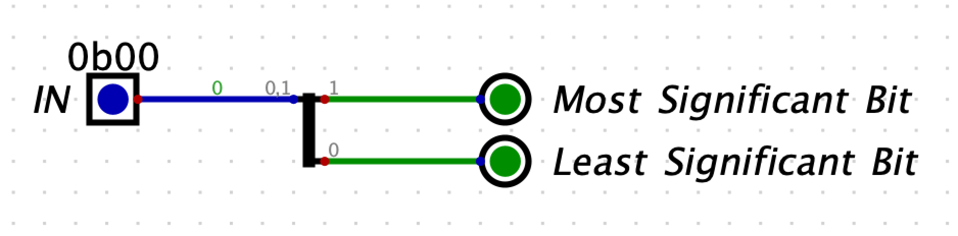
Splitters allow you to take a multi-bit value and split it up into smaller parts, or (despite the name) combine multiple values that are one or more bits into a single value. Here, we split our 2-bit input into two 1-bit values:
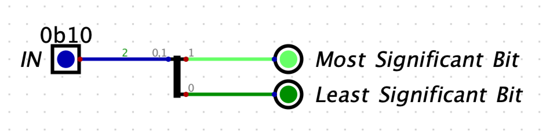
You can see when our input is 0b10, only our MSB output lights up:
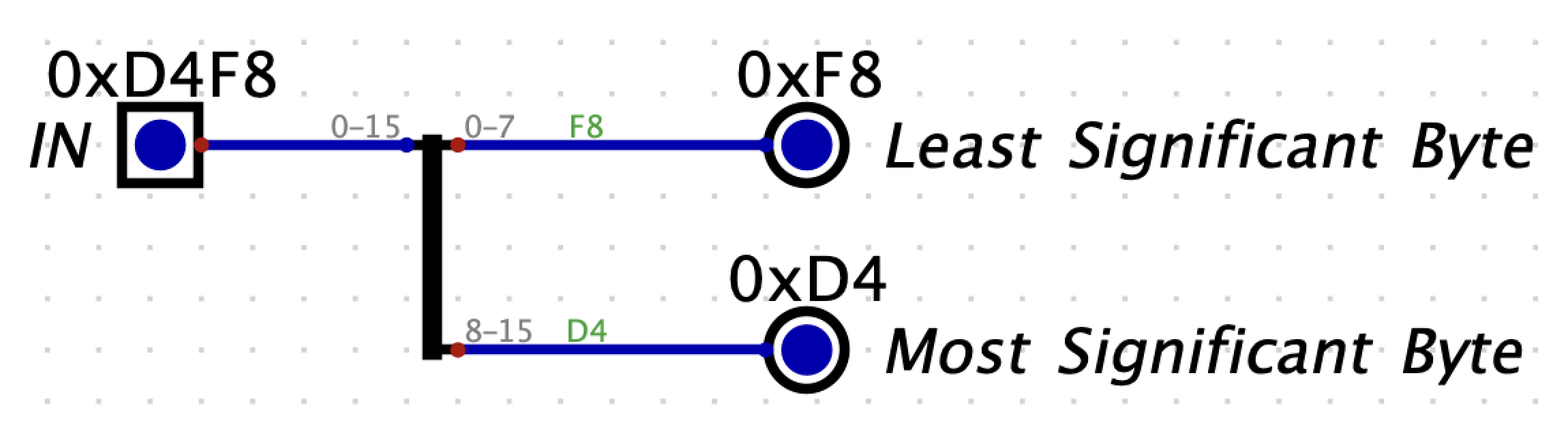
Here is another example where we have a 16-bit input. The input is then split into 2 bytes:
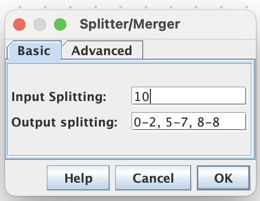
We don’t have to split the values evenly - it is possible to split an input into various group sizes - and you don’t have to use all the bits. Here is an example where we take a 10-bit input and split it into bits 0-2, 5-7, and 8.
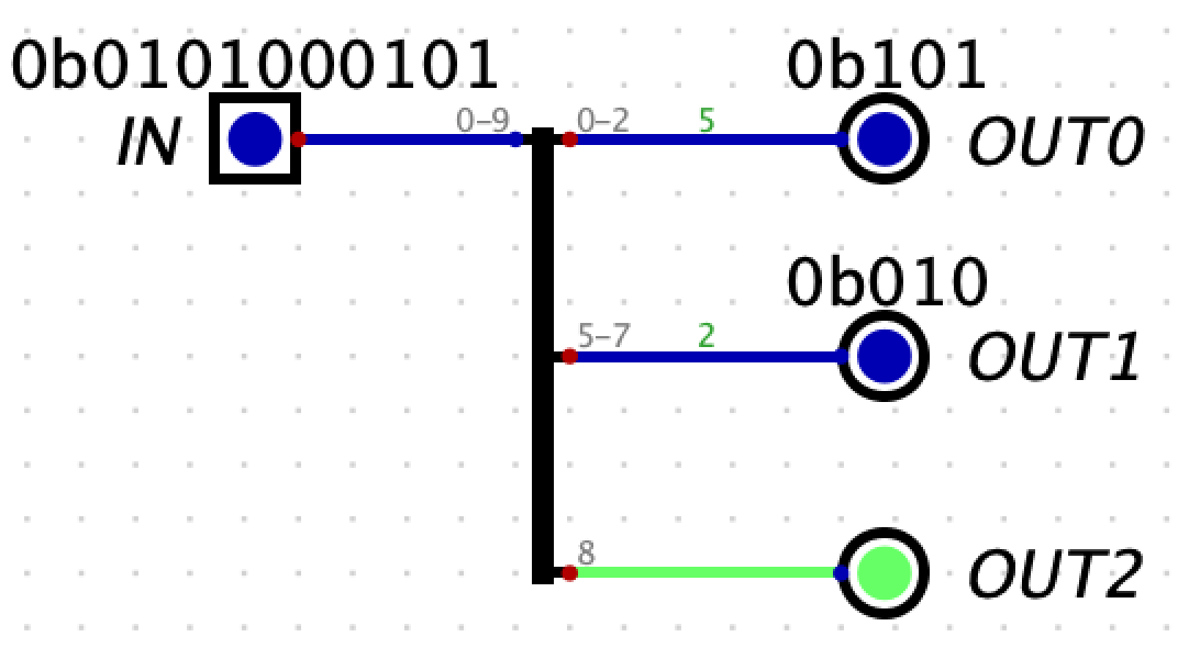
Build the above circuit yourself in the file
ex2-0.dig.
Do not modify the names of the input or outputs!!!.
Step 1: Configure the splitter. You can find the
splitter by clicking
Components -> Wires -> Splitter / Merger. Right click
(or double tap) the splitter to change the input and output splitting as
seen in the following screenshot. If you would like to change the
spacing between the outputs, you can do this by going to
Advanced -> spreading -> and selecting the desired
spacing.
Step 2: Configure the inputs and outputs. The bit
width of the inputs and outputs must be compatible with the splitter. To
change the bit width, right click (or double tap) the input/output, and
use the Data Bits field to set the bit width. For example,
the input should be 10 bits.
If the bit widths of your input and outputs do not match their corresponding connections with the splitter, you will get an error when you try to simulate the design in the next step.
Step 3: Simulate your design. Click the play button
in the top bar to start the simulation. To change the value of the
input, right-click it and set the input field to the
desired value. When you click Apply, you should see the
outputs change. Notice that by default, the values are displayed in
decimal. If you would like to change the base of the number being
displayed, stop the simulation, right click the output, go to the
Advanced tab, and under Number Format select
the desired base.
A test fixture is included for you to verify the functionality of your circuit. To run the test fixture, click Simulation -> Run Tests.
A new window should appear showing you the results. If you pass all test cases, all outputs will be highlighted in green as shown below.

Notice, there are two test cases. In the first test case,
IN = 0x1D5. The expected outputs are
OUT0 = 0x5, OUT1 = 0x6, and
OUT2 = 0x1. In the next test case, IN = 0x22A.
The expected outputs are OUT0 = 2, OUT1 = 1,
and OUT2 = 0.
Using what you just learned about splitters, build a circuit that
outputs true if a 10-bit value is negative and odd. All values are
encoded in 2’s complement. Build your implementation in
ex2-1.dig.
Do not modify the name of the input or output pin provided in the file!!! Doing so will cause the autograder to fail.
A test fixture is included for you to verify the functionality of your circuit. To run the test fixture, click Simulation -> Run Tests.
A new window should appear showing you the results. If you pass all test cases, all outputs will be highlighted in green. Even if everything works the first time, make sure you understand what the test is checking.
In this exercise, you will build a circuit that will output 1 if A
> B, and 0 if A <= B. A and B are both two-bit unsigned numbers.
Additionally, define A1 and B1 as the msb of A and
B respectively, and A0 and B0 as the lsb of A and
B. Build your design in ex3.dig.
Build your circuit in Digital. Ensure you use tunnels to simplify your diagram.
Do not modify the name of the input or output pin provided in the file!!! Doing so will cause the autograder to fail.
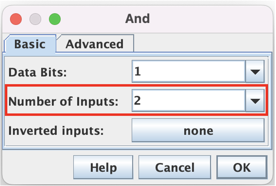
To change the number of inputs to a gate, right click (or double-tap) the gate. Then select the desired number of inputs in the drop down.
A test fixture is included for you to verify the functionality of your circuit. To run the test fixture, click Simulation -> Run Tests.
A new window should appear showing you the results. If you pass all test cases, all outputs will be highlighted in green. Even if everything works the first time, make sure you understand what the test is checking.