Encumbrance-free Telepresence System with Real-time 3D Capture and Display using Commodity Depth Cameras
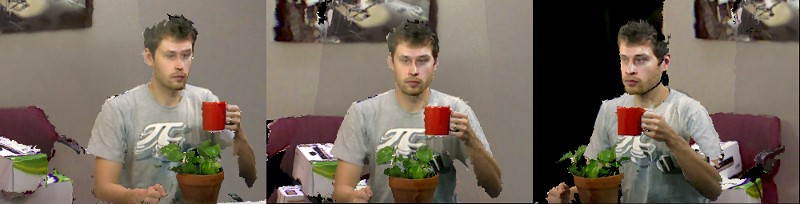 |
| Figure 1: Three views of a live capture session.
|
Abstract
We introduce a proof-of-concept telepresence system that
offers fully dynamic, real-time 3D scene capture and continuous-viewpoint, head-tracked stereo 3D display without requiring the
user to wear any tracking or viewing apparatus. We present
a complete software and hardware framework for implementing
the system, which is based on an array of commodity Microsoft
KinectTM color-plus-depth cameras. Novel contributions include an
algorithm for merging data between multiple depth cameras and
techniques for automatic color calibration and preserving stereo
quality even with low rendering rates. Also presented is a solution to the problem of interference that occurs between Kinect cameras with overlapping views. Emphasis is placed on a fully
GPU-accelerated data processing and rendering pipeline that can apply
hole filling, smoothing, data merger, surface generation, and color
correction at rates of up 100 million triangles/sec on a single PC
and graphics board. Also presented is a Kinect-based markerless
tracking system that combines 2D eye recognition with depth information to allow head-tracked stereo views to be rendered for
a parallax barrier autostereoscopic display. Our system is affordable and reproducible, offering the opportunity to easily deliver 3D
telepresence beyond the researcher's lab.
Overview
 |
|
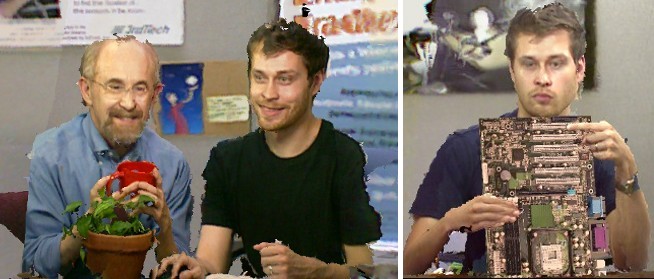
Figure 2. Applications. Left: Multi-user telepresence session. Right: Mixed reality collaboration -- A 3D
virtual object (circuit board) is incorporated into a live 3D capture session and appropriately occludes real objects.
|
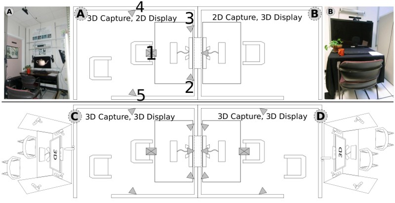 |
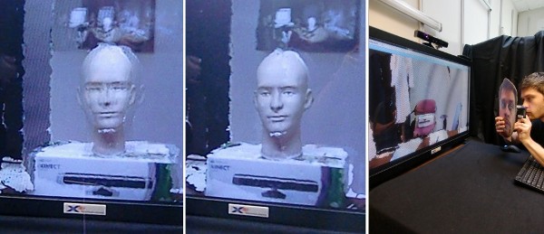
| Figure 3: Physical layout. Top: Demonstrated proof-of-concept system configuration. Bottom: Proposed ideal configuration. |
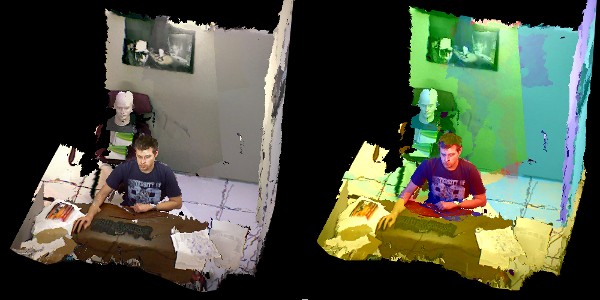 |
| Figure 4: Camera Coverage. Left: System Camera coverage (5 cameras). Right: Color-coded camera contributions. |
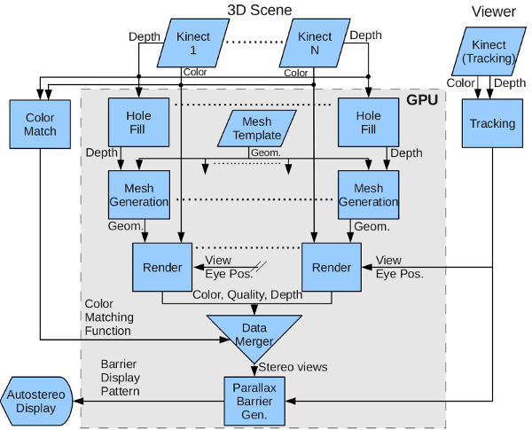 |
| Figure 5: Data Processing and Rendering Pipeline. All real-time graphics functionality is implemented on the GPU. |
 |
|
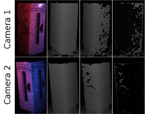
Figure 6: Kinect interference problem. First column: IR images showing combined projected dot pattern from camera 1 (red dots) and
camera 2 (blue dots). Second column: depth images with no interference. Third column: depth images with interference from other
camera. Fourth column: Difference of second and third columns. |
 |
|
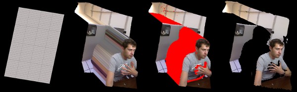
Figure 7. Fast Meshing for the Kinect. Left to right: 1) Triangle mesh template stored in GPU memory. 2) Vertex shader extrudes template using camera intrinsics and depth texture. 3) Geometry shader rejects triangles corresponding to missing or discontinuous surfaces (shown in red). 4) Resultant textured mesh. |
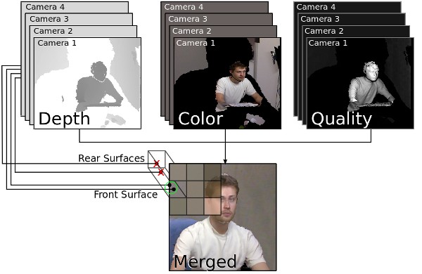 |
Figure 8. Data Merger Algorithm. Depth, color, and quality estimate values are determined at each pixel for each camera. The front surface is determined using the depth information, and the associated color values are weighted by the quality estimates. |
 |
|
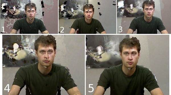
Figure 9. Data processing results. 1: No enhancements applied. 2:
All enhancements except hole filling. 3: All enhancements except
color matching. 4: All enhancements except quality weighted data
merger. 5: All enhancements applied. ("All enhancements" includes
to hole filling, data merger, and color matching) |
 |
|
Figure 10. Head-tracked stereo in motion. Left: Tracking prediction,
intra-frame rendering disabled. Center: Prediction, intra-frame rendering enabled. Right: Head cutout used to test eye tracking, with camera
behind eye. |
Contact
Andrew Maimone, Graduate Student
maimone (at) cs.unc.edu
Paper
Coming Soon.
Frequently Asked Questions
Q: Is this really 3D, or does it just provide a view from the user's head position?
A: It is both. The system displays the scene in stereoscopic 3D (each eye sees a different image), providing a
similar sense of depth as current 3D TV and 3D cinema, but does not require glasses. The system also allows the
user to "look around" the scene.
Q: How is this different than earlier Kinect 3D video capture?
A: Earlier Kinect video capture utilized one or two Kinect units, which do not provide enough coverage to allow a
user to look around a small room without large missing areas. Additionally, when using two Kinect units the data
was not smoothly merged, presenting quality problems. Utilizing more Kinects presents a challenge since the units
interfere with each other, causing holes to appear in the output. Our current system utilizes five Kinect units to
provide more comprehensive scene coverage and new algorithms to overcome the interference problem and merge data
with improved quality.
Q: Why not just use the 3D cameras used for 3D cinema?
A: The cameras used for 3D cinema are essentially two 2D cameras placed side-by-side. They allow a scene to be
captured from a single general viewpoint at two slightly different positions, one for each eye. However, by
themselves these cameras do not provide the depth information necessary to allow the user to "look around" the
scene.
Q: Why does a teleconferencing system need to be in 3D and allow the user to look around the remote scene? Is this
just a gimmick?
A: The value of these features is two-fold. First, they increase the sense of "presence" or "being there", the
feeling that one is actually co-located with the remote user and his or her environment. This sense helps the user
forget he or she is looking at a display screen and communicate naturally as if talking to someone on the other
side of a table. Second, the ability to "look around" the scene helps preserve information that is lost during
normal 2D video conferencing. For example, imagine that you are seated in a meeting room and someone's head is
blocking your view of a whiteboard. In our system, as in real life, you would naturally move your head around for an
unobstructed view. In traditional video conferencing, you must interrupt the meeting and ask that the remote user
move his or her head. As another example, imagine an engineer is holding up a new prototype part to show to a
remote participant. With our system, the remote participant could simply move his or her head around to inspect the
part. With traditional 2D video conferencing, the remote participant must communicate back and forth with the
engineer regarding the different angles the part should be held until it is fully inspected.