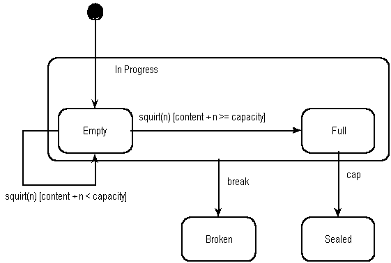
State transition diagrams have been used right from the beginning in object-oriented modeling. The basic idea is to define a machine that has a number of states (hence the term finite state machine). The machine receives events from the outside world, and each event can cause the machine to transition from one state to another. For an example, take a look at figure 1. Here the machine is a bottle in a bottling plant. It begins in the empty state. In that state it can receive squirt events. If the squirt event causes the bottle to become full, then it transitions to the full state, otherwise it stays in the empty state (indicated by the transition back to its own state). When in the full state the cap event will cause it to transition to the sealed state. The diagram indicates that a full bottle does not receive squirt events, and that an empty bottle does not receive cap events. Thus you can get a good sense of what events should occur, and what effect they can have on the object.
State transition diagrams were around long before object modeling. They give an explicit, even a formal definition of behavior. A big disadvantage for them is that they mean that you have to define all the possible states of a system. Whilst this is all right for small systems, it soon breaks down in larger systems as there is an exponential growth in the number of states. This state explosion problem leads to state transition diagrams becoming far too complex for much practical use. To combat this state explosion problem, object-oriented methods define separate state-transition diagrams for each class. This pretty much eliminates the explosion problem since each class is simple enough to have a comprehensible state transition diagram. (It does, however, raise a problem in that it is difficult to visualize the behavior of the whole system from a number of diagrams of individual classes - which leads people to interaction and activity modeling).
The most popular variety of state-transition diagram in object methods is the Harel Statechart as in Figure 1. This was introduced by Rumbaugh, taken up by Booch and adopted in the UML. It is one of the more powerful and flexible forms of state transition diagram. A particularly valuable feature of the approach is its ability to generalize states, which allows you to factor out common transitions (thus I can show that the break event applies to both full and empty states by creating the super-state of in-progress). It also has a flexible approach to handling processing. Processes that are instantaneous (i.e. cannot be interrupted) can be bound to the transitions or to the entry or exit of a state, these are called actions. Processes that are long (and can be interrupted) are bound to states, these are called activities. Transitions can also have a condition attached to them, which means that the transition only occurs if the condition is true. There is also a capability for concurrent state diagrams, allowing objects to have more than one diagram to describe their behavior.
Figure 1: A Harel statechart
Not all methods use Harel Statecharts. One of the most notable
dissenters is Shlaer/Mellor who use a simpler Moore model state
diagram. This form only allows processes to occur when in a state
(hence the extra state in Figure 8) and has no superstates. This
is a good example of the question of expressiveness in techniques.
The Harel Statechart is clearly a more expressive technique, but
since it is more expressive there is more to learn when using
it. In addition, it is more difficult to implement. Shlaer/Mellor
take the view that since state diagrams do not get too complex
when drawn for a single object, the extra expressiveness is not
worthwhile.
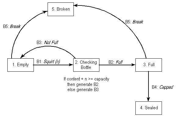
Figure 2: Moore model state diagram as used by Shlaer/Mellor. It is the equivalent to figure 1.
State models are ideal for describing the behavior of a single object. They are also formal, so tools can be built which can execute them. Their biggest limitation is that they are not good at describing behavior that involved several objects, for these cases use an interaction diagram or an activity diagram.
People often do not find drawing state diagrams for several objects to be a natural way of describing a process. In these cases you can try either drawing a single state diagram for the process, or using an activity diagram. This defines the basic behavior, which you then need to refactor to split it across a number of objects.
UML uses Harel statecharts, which have also become the most popular
style of state diagrams in object methods. For an initial tutorial
on them I would suggest either [Booch] or [Rumbaugh]. For a more
in-depth treatment take a look at [Cook and Daniels]; they give
a lot of good details on formalisms, an integration of design
by contract, and a discussion of the use of state diagrams with
subclassing.